CAN FD protocol
Adding FD (Flexible Data rate) support for CAN bus decoderA couple of years ago, Bosch have released a new version of their famous CAN bus protocol, called CAN FD (FD stands for Flexible Data rate). Today, CAN-FD is quickly replacing all older CAN bus systems. To continue supporting our users in their daily debugging tasks, we have updated our CAN bus protocol analyzer to support latest CAN FD.
Working with CAN FD can be complicated (much more than standard CAN). A logic analyzer like the SP209i can be very useful to understand how your CAN system is working, or why is it not working.
What’s even more important that the logic analyzer device itself, is the software and the protocol analyzer.
But, What is CAN bus?
CAN bus a is communication protocol widely used in automobile and various industrial applications. It allows a master device (like a micro-controller) to communicate with multiple slave devices (like sensors) over a very long distance (maximum distance depends on bit rate used and bus design, but can usually be in the order of hundreds of meters). Unlike other protocol that only specify the physical layer (like RS232), the CAN bus specifies many layers of the network. As a matter of fact, CAN bus specifications covers data packetization and protection using various mechanisms like bit-stuffing and a CRC word at the end of the data frame.
More about CAN-FD
CAN FD protocol can be quite complicated, specially if you have to deal with the complexity of the hardware and firmware implementation. For instance, CAN-FD relies on various kinds of bit stuffing mechanisms (as compared to standard CAN where only one bit-stuffing mode is used).
Implementing a working CRC can be tedious. Now if a CRC is not complex enough for you, imagine having 3 different CRC polynomials depending on the number of bytes in a CAN frame, and two different bit-stuffing algorithms depending on the position of a bit in the CAN bus frame.
That’s where a good logic analyzer kicks in!
ScanaStudio to the rescue!
ScanaStudio logic analyzer software has a large range of protocol analyzers, including the CAN protocol. Protocol Analyzers are written to provide as much information and assistance to the hardware designer as possible, and CAN bus is no exception.
To get your CAN based system quickly debugged, start by connecting one of our Logic Analyzers to your CAN H and CAN L lines (or simply connect to the CAN line between the MCU and CAN transceiver).
Dedicated CAN receiver
Some logic analyzers have integrated CAN receivers and can be directly connected the CAN Bus differential lines pair. For instance, the SP209i (industrial) logic analyzer lets you directly connect to CAN bus lines (CAN H and CAN L). On the other hand, with the SP209 (standard) logic analyzer, you have to connect the logic analyzer to a CMOS compatible signal (a single-ended signal, operating on 1.8V to 5V level).
It’s good practice to capture some activity - any CAN bus activity - before going further to make sure your device is correctly configured and that’s you’re seeing CAN bus signals on the screen as expected.
CAN protocol analyzer
Then, add a CAN protocol decoder and configure it correctly, choosing the right channel and the right baud-rate. If you don’t know the baud rate, you can simply measure the bit time from some captured frames. Please note that in case of CAN-FD protocol, you also have to configure the (higher) Flexible bit rate
Expanding the “Display options” tab lets you configure how each part of the frame is displayed:
For example, in your specific application, it may make more sense to display CAN ID fields in binary format and data fields in decimal format instead of Hexadecimal format.
Exploiting the results
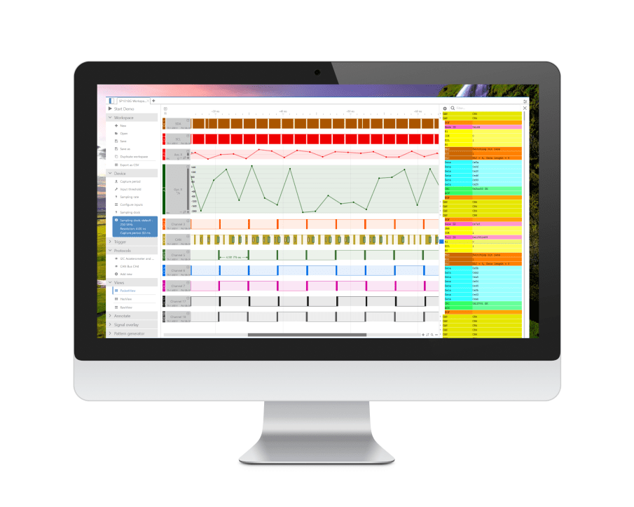
Once the decoder is added to the workspace, you’ll notice that “decoded items” appear on top of the CAN signals, as in the image below:
You’ll also notice that the correct CRC is highlighted in green color. In case of a wrong CRC, it would be highlighted in red.
If you hover your mouse over any decoded item, you’ll notice some additional details, namely sampling points (as well as bit stuffing samples that are ignored bits):
Now, I’ll let you open the HEX-View and Packet-View to discover new ways of digging through CAN frames!