Logic Analyzers manual
What is a logic analyzer
There is a lot of history around logic analyzers. While Wikipedia covers the early days of logic analyzers on this page https://en.wikipedia.org/wiki/Logic_analyzer, we’re going to present how the logic analyzers have evolved to what they are today.
Logic analyzers are measurement devices - just like oscilloscopes or voltmeters - that are used to measure the variation of logic level over a period of time. By logic level, we imply that we’re only interested in knowing the binary state of a digital signal: 0 or 1, and unlike oscilloscopes, logic analyzers are not designed to look at analog voltages (like a sine wave).
Now to be fair, all electronic signals are “analog signals” and there is no such thing as a pure logic signal without any noise or overshoot. Although a logic analyzer will display captured signals as perfect square-shaped signals, complicated circuits in the logic analyzer hardware convert the analog signals to digital (logic) signals.
The image above shows how an analog signal (a) is converted to a digital signal (b). typically, the front-end circuit of a logic analyzer will implement some kind of hysteresis using two thresholds (V High and V Low) to filter out glitches and noise.
While a logic analyzer will typically store much fewer details about a signal compared to an oscilloscope, it will capture and store signals for a much longer period. That’s what we call “capture depth”. Some logic analyzers will even capture signals for an unlimited time, that is until the user manually stops the capture.
Logic analyzer applications
A logic analyzer is used to diagnose and debug digital circuits and embedded systems. Logic analyzers are must-have tools if you’re working with micro-controllers, FPGAs or other electronic circuits, as they will allow you to visualize the signals generated by firmware, a sensor or any similar digital circuit. Typically, one will use a logic analyzer to ensure that components are behaving correctly - e.g. an I2C device is responding to a microcontroller request - and rectify the embedded firmware in consequence.
Below is an example capture of RS232 (Serial UART), captured by an Ikalogic logic analyzer device, and decoded using ScanaStudio software:
Obviously, logic analyzers can also be used for reverse engineering applications.
Capture depth is one of the major features that characterize a logic analyzer as it helps understand the full chain of events that led to a particular behavior or event.
Ikalogic devices
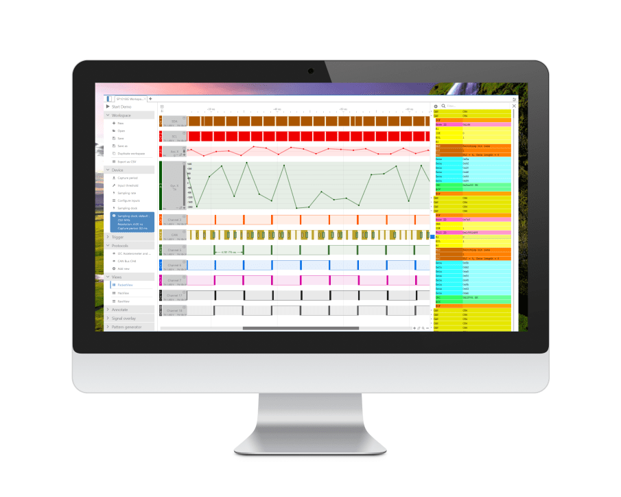
Ikalogic provides logic analyzers that connect to a computer via a USB cable. A free software - called ScanaStudio - is used to configure the device and display captured signals. The software can also be used to further analyze the captured samples by decoding protocols like I2C, SPI or UART.
ScanaStudio software
ScanaStudio is a free software used to view and analyze signals captured with Logic Analyzer devices. Devices are connected to the host computer via USB and transfer captured data to ScanaStudio. Some devices stream data in real-time (like the SP209 series logic analyzer), other devices (like the SQ Series store data in their internal memory buffer before transferring data after capture is done.
ScanaStudio is also used to configure the logic analyzer device, like setting up the trigger conditions and configuring parameters like the sampling rate and the number of samples.
For some devices that have the ability to generate samples (like the SQ series), ScanaStudio is also used to build the logic patterns to be generated.
In other terms, ScanaStudio is the user interface of all Ikalogic Logic Analyzers. For this reason, this manual will mainly address the software part.
Over the years, ScanaStudio has evolved to offer highly advanced features like protocol decoding, signals editing, packetized view and data filtering.